
AgIRoM Build Guide (In Progress)
Hi! This is AgIRoM, a replicated hardware platform for agile vision-based autonomous flight. Credits to UZH Robotics & Perception Group’s work, as this platform largely builds from their own platform (Agilicious). AgIRoM explores the potential for drones that can navigate unknown, changing environments utilizing completely internal computation (onboard computers, computer vision, etc. ~ i.e. no external odometry/processing). On this page, you will find helpful information regarding how the platform works, and how to build/develop it!
If used in academic context, citation information for Agilicious found here.
UZH RPG Agilicious Overview
UZH’s Robotics and Perception Group recently open-sourced their Agilicious Platform. Agilicious contains both instructions and code to replicate the hardware platform that UZH have been using in their own research. More specifically, it provides a ‘standardizable’ approach to developing agile autonomous vision-based drones. This entails the inclusion of custom controllers, bridges, estimators, safety pipelines, simulators, and references. Akin to IRoM’s own goal of having modular pieces of hardware that can be used in research applications, AgIRoM was built both as a means to conduct UAV research, but also to further the process of standardizing a platform (namely, UZH RPG’s).
Their repo can be found here –> Link to UZH Agilicious: https://github.com/uzh-rpg/agilicious [need to request access].
Hardware
*It should be noted that AgIRoM is the platform’s name, not the drones’ names. Consequently, the builder of each respective quad is held responsible for naming it. For inspiration, some examples from UZH Agilicious have been “kingfisher,” and “challenger.”
Purchase List –> reach out if you’d like a copy of our purchase list!
Betaflight Configurator Basics and Setup
You can install BTFL here. I would recommend getting the portable version as it is cleaner to uninstall (not a big deal, but if you use the regular installer and at some point you want to upgrade your configurator - to download a new version, you have to completely remove the old files - or just uninstall, you need to run the uninstaller executable - you can’t manually uninstall through any other means as it won’t clean up all the files correctly).
The important configuration steps required for Betaflight are inputting the Agilicious-specific parameters in the CLI interface, and setting up the serial ports on the ports tab. For Betaflight FCs (or most UART-enabled devices), only one function can be used on each UART port. Each UART port will have one RX, and one TX - the idea being you can’t use both RX1 and TX1 at the same time, for example. Instead, you would need to use either RX1 + TX2, or RX2 + TX1. In the ports tab, you will need to toggle Serial RX to ‘ON’ for the respective RX pad you soldered to on the fligt controller, and set telemetry output to ‘MAVLINK’ for the TX pad you soldered to. For example, if you used the RX2 pad, and the TX6 pad of the FC, you will need to set Serial RX to ‘ON’ for UART2, and ‘MAVLINK’ telemetry for UART6. Do not mess with the USB VCP port unless you know what you are doing - this is the port that enables the flight controller to be connected to a computer.
For the Betaflight Parameter configuration, you can refer to Agilicious’ BETAFLIGHT_PARAM.INI file for the most part, but note that only a subset of the parameter definitions in there are actually required (since it is a dump file - some settings are just the defaults). Copying and pasting the file is not recomended as you will run into many version conflicts and deprecated settings. The relevant sections are: the rateprofile settings, the PID tuning settings, the channel mapping (TAER1234), and the serial RX protocol (make sure it’s SBUS).
Building the Quad
CAD files can be found here. Includes mounts/cases for Boson + Orin NX, T265, D435, and battery. Feel free to redesign any of the existing parts! One piece of advice I would give to those newer to CAD design, a good start to designing mounts and fittings for existing parts is to try find CAD models to design around. For example, to design the Jetson Orin NX housing, I found CAD models of the board from from their website and was able to easily design a mounting case, in addition to easily adding tolerances to certain fits from actual measurements. To build the quad, you will need M# hardware (nuts, bolts, nyloc nuts, heat set inserts), zipties, and the relevant parts listed in the purchase list. Refer to the following images for general build steps:
[add photos next time when build new quad]
Wiring
Agilicious uses serial UART to interface communications between the High-Level and Low-Level computers (Jetson Orin NX <=> Betaflight Flight Controller). In AgIRoM’s case, this requires you to wire the RX/TX pads of the respective devices to each other (Note: typically, power cables for example would just wire + to +, and - to -, but in UART’s case, you instead have to wire RX of one device to TX of the other and vice versa. Think of it as defining receiving and transmitting ends). If using the Boson Carrier Board + Orin NX and the SpeedyBeeF7 V3 flight controller for example, just simply find the RX/TX pins and pads on each device and wire them accordingly (manuals can also be found below in the Misc. Manuals section). Your choice of hardware may differ, and consequently the wiring may differ slightly, but ultimately the process is the same. Be sure to find out further configuration steps required to use the respective UART ports on each device –> e.g. steps to configure the serial interface for Orin found in the next section, and steps to toggle UART ports for specific purposes (telemetry, serial RX) found in Betaflight setup section.
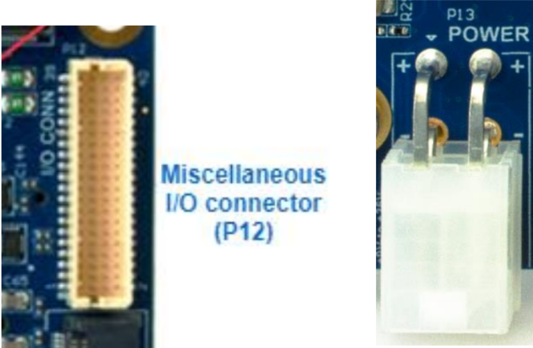
For example, the relevant ports you will need to wire on the Boson carrier board are the power plug, and the IO connector. One interesting thing to note is that the Boson’s power connector has redundant power and ground terminals - you can simply just splice the respective matching wires together into a Y junction. This will not affect the power distribution of the board. For the IO ports, you can refer to the Boson Carrier Board Manual PDF to find the respective UART pins. The pins are numbered from 1 (bottom left) to 40 (top right), with odd pins on the left and even pins on the right. Make sure to note down which pins are used for RX# and TX# so you can input the correct serial addresses later. Additionally, make sure you are connecting the ‘opposites’ of the Orin and FC (as in wiring RX to TX, not RX to RX, etc.).
Jetson Orin NX start guide
Booting up the Orin
First things - the Orin NX 16GB module does not have internal storage. Consequently, it relies on an external storage device on the carrier board to store the OS. However, SD cards will not work with the Boson Carrier board / Orin NX combo used in our version (Orins do not have SDIO configured). You will need to install an NVMe SSD storage card on the underside of the Boson carrier board. Once it has been inserted into the M.2 Key slot, alongside inserting the Orin NX module in place, you can begin the bootup process.
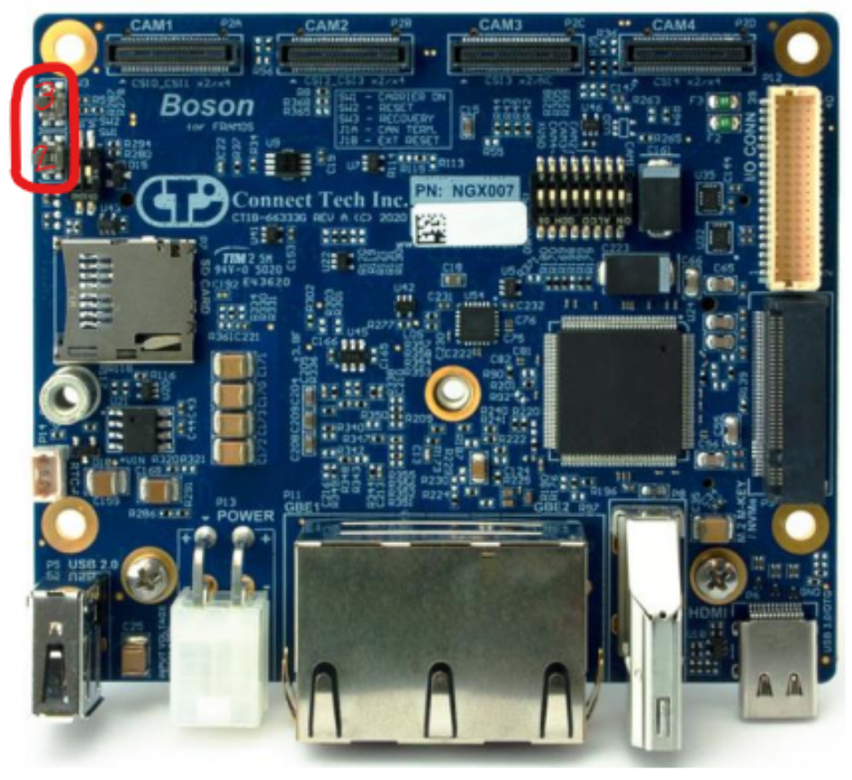
Refer to the Boson carrier board’s manual for switches 2 and 3 locations - these are important, and act as the reboot, and force recovery pushbuttons respectively.
You will be using (https://connecttech.com/resource-center/kdb373/) to install the OS on the Orin NX. This step requires a “host” Linux computer with at least 40GB of free space. Peripherals you may find useful during this process include a mouse, keyboard, HDMI output to monitor, and an Ethernet connection.
To put the Orin NX in force recovery mode, simply hold down both switch 2 and 3, then release 2 whilst still holding 3, and then after a second, release switch 3. To verify that the device is in force recovery mode, whilst connected to the host computer via USB-C - type ‘lsusb’ into a terminal, after which if you have successfully put the device in force recovery mode, an NVIDIA device will be shown in the output (refer kdb373 guide). After flashing the OS successfully, you can follow (https://connecttech.com/resource-center/kdb374/) to install the extra SDK components.
During the flashing process (OS, SDKs), you may run into some kind of mount.nfs issue where the SDK manager will halt at the SSH step of the flashing. One possibility is due to the firewall being active. A quick fix for this is to temporarily disable the firewall of the host computer:
sudo ufw disable
Just remember to enable it again after (use ‘enable’ instead of ‘disable’).
Serial Configuration
Stuff to add: checking tty* ports available, finding which address corresponds to which port, adding user to dialout group, and useful terminal commands
Measuring physical parameters of quad (weight, inertia matrix, max motor thrust/rpm, etc.)
Misc. Manuals
SpeedyBeeF7 V3 PDF Manual
ConnectTech Boson Carrier Board for Jetson Orin NX (*IO expansion header pinout - for UART pins - on pg. 22-23)
Oscar Liang Flight Controller Basics
UART Basics
Getting started
Software Environment Setup
–> Link to UZH Agilicious: https://github.com/uzh-rpg/agilicious [need to request access]. The main page contains pretty straightforward details on compiling the workspace/code and steps for launching first vision-based flight.
Dependencies and Misc. required installations
- Wifi: To connect the Orin NX to wifi, one option is to use an ethernet connection. However, this is only useful for the first few steps where being tethered by a wire is not a problem because you aren’t actively flying the drone. ConnectTech’s website refers to a wifi/bluetooth adapter for M.2 E-key wifi cards. Your other option is to use a USB wifi adapter - something similar to an Archer T2U Nano AC600. These both should work fine, with a few additional software steps for the USB route:
You will need to install the drivers for the AC600: I’ve found that both of these guides work interchangeably on occasion. Not sure which is the correct one to be honest, but one of them should work: rtl8188au / rtl8188eu. Before doing this step, the Github pages will mention the need to install kernel headers for your system. If the boards you use do not install kernel headers by default (e.g. the Boson - Orin NX combo we use), you can follow this to install them. Try a few of the suggested commands here (sometimes some just work, and others don’t).
- Librealsense: If you are using the T265, you will notice that it is ‘deprecated’ and no longer supported by Intel. This means the code for it has been removed from the newer versions of Librealsense. If you haven’t made the switch to the D435i yet (TBD ~ future update here), you will need to install an build an older version of librealsense to interface with the T265. The following commands can be used to build v2.53.1:
# modified from solution posted here: # https://forums.developer.nvidia.com/t/problem-installing-intel-d435-camera/252862 git clone -b v2.53.1 https://github.com/IntelRealSense/librealsense/ cd librealsense/ # command may differ depending on how/where folder is cloned ### Install as needed... sudo apt install libudev-dev pkg-config libgtk-2-dev sudo apt install libudev-dev pkg-config libgtk-3-dev sudo apt install libusb-1.0-0-dev pkg-config sudo apt install libglfw3-dev sudo apt install libssl-dev sudo apt-get install libglfw3-dev libgl1-mesa-dev libglu1-mesa sudo apt install cmake ### sudo cp config/99-realsense-libusb.rules /etc/udev/rules.d/. sudo udevadm control --reload-rules && udevadm trigger mkdir build cd build/ cmake ../ -DBUILD_EXAMPLES=true make sudo make install cd tools/realsense-viewer ./realsense-viewer - Some more misc. steps along the way:
sudo apt install ros-$ROS_DISTRO-mavros # (installing mavros to get telemetry data from FC)
sudo apt install ros-$ROS_DISTRO-realsense2-camera # (installing realsense2_camera for t265)
sudo /opt/ros/$ROS_DISTRO/lib/mavros/install_geographic_datasets.sh # (installing geographiclib datasets ~ after catkin building the workspace, and before running vision-flight code; don't forget to re-source ros and catkin workspaces)
Agilicious Docker Guide
Useful to avoid dependency/version conflicts. You can follow their steps for the most part ~ the step to run the docker container is a little unclear, but after you cd into the launch_container.sh directory, you can run
sudo sh launch_container.shto start the docker. Note that when you run the docker container, it creates an instance based on the defined ‘image’ of the container. This image is static and does not update inside the docker. As such, to save changes to the docker container (i.e. updating the ‘image’ s.t. running the docker commands will build a container based on the updated image), you will need to open a new terminal. To check active running docker images, you can use this command:
sudo docker psTo update the current docker image with any added changes you want to keep, you can use:
sudo docker commit <container_id> ros_agilicious:latestwhere <container_id> is replaced by the CONTAINER ID string found by checking the running docker containers.
Config / parameter files
Agilicious contains many different config files, each specifying different run parameters. Knowing which to use, what each do, and which lines to edit is important, as plugging in a different config file without knowing what it does can be catastrophic (e.g. don’t randomly sub in ekf_full_imu.yaml for the default ekf_full_no_imu.yaml in the pilot config definition, as this causes the T265’s uptilt to be accounted for in the estimator and subsequently aggressively pitch the quad during takeoff - leading to a pretty fatal crash).
The important ones you’ll need to edit to get the code running are outdoor_betaflight_pilot.yaml, sbus.yaml, and betaflight.launch. In outdoor_betaflight_pilot.yaml, you’ll need to sub in your “quadrotor” yaml file (default is kingfisher.yaml ~ these specify physical parameters of quad like weight, inertia, etc.); you will need to create one for each ‘new’ quad design you build. For sbus.yaml and betaflight.launch, you will need to specify the serial address each file is interfacing with. These addresses correspond differently for different carrier boards, but there should be a unique one for each UART port used. Make sure to put the UART address that corresponds to sending out data (TX) in the sbus.yaml file, and the UART address that corresponds to receiving data (RX) in betaflight.launch. This is done accordingly so because SBUS is the signal being sent out, whereas the betaflight mavros interface is used to receive telemetry input.
Safety
Whilst the prospect of getting the platform up and flying is exciting, there are key safety checks and guidelines that you will need to ensure before flying.
- This doesn’t directly apply to flying, but when doing tests on the bench, remove the propelors - sometimes unexpected/stray signals will get sent to the motors, and having the propellors still on can be very dangerous.
- Setting up a perimeter: Agilicious’ code does offer a ‘virtual’ safety net. This is defined by coordinates set inside the arena guard yaml files (specific files will vary depending on if you are using VICON, or solely the T265’s odometry). If possible however, it is always a good idea to set up a physical safety net for the safety of the people/equipment in the surrounding space of the lab environment. The bonus is that if it crashes into the net, the props will likely get snared meaning you won’t have to build a new quad. For either of these safety measures, you still need to understand that Agilicious/AgIRoM are very fast moving objects that carry a lot of momentum. If you set a perimeter, be sure to add an extra layer of ‘cushioning’ (e.g. a physical safety net that is too close to the walls won’t really stop the quad from crashing into the wall, and the precision of the virtual safety net can only be so accurate ~ if the quad is crashing, it’s likely the position estimate has been failing anyways).
- Most manually controlled hobby quads will have a ‘kill switch’ - Agilicious’ GUI will typically have a big red ‘OFF’ button. This button will completely disable the quad from receiving any inputs, and kill the motors. This means if it is flying, the quad will drop from the air. Whilst this is not ideal as doing so will cause the quad to crash in most cases, it is necessary if the quad has lost control and doing so may prevent further damage.
Launch your first real flight!
For ‘Vision-Based Flight,’ the Pilot will use the T265’s VIO data for state estimation. By default, this information is not streamed so you will need to add a few lines of code to toggle these arguments on. In the t265_only.launch file, you will need to add the following as args:
<arg name="enable_accel" value="true"/>
<arg name="enable_gyro" value="true"/>
<arg name="enable_pose" value="true"/>
Doing so will start the pose stream, which can be confirmed by reasonable odometry values shown on the GUI when running the code.
To run the base code, you will need a basecomputer which will be used to communicate with the Orin. Run the following commands on both the Orin and basecomputer:
*NOTE: Desktop/Laptop and Drone must be on SAME wifi network.
Commands for Basecomputer
If you’re using a docker container:
cd agirom/agilicious_internal/scripts
sudo sh launch_container.sh
else, you only need the following:
cd catkin_ws/src/agilicious_internal/agiros/agiros/launch/real_world
source /opt/ros/melodic/setup.bash
source ~/catkin_ws/devel/setup.bash
export ROS_IP=<IP_OF_THIS_DEVICE>
export ROS_MASTER_URI=http://<IP_OF_MASTER_HERE>:11311
roslaunch outdoor_basecomputer.launch quad_name:=agirom
Commands for Quad (ssh from basecomputer in a different terminal)
ssh agirom@<IP_ADDR_OF_ORIN>
cd catkin_ws/src/agilicious_internal/agiros/agiros/launch/real_world
source /opt/ros/noetic/setup.bash
source ~/catkin_ws/devel/setup.bash
export ROS_IP=<IP_OF_THIS_DEVICE>
export ROS_MASTER_URI=http://<IP_OF_MASTER_HERE>:11311
roslaunch outdoor_quadrotor.launch quad_name:=agirom
++ Designate either the quad or the basecomputer as the master, and use that device’s IP address for <IP_OF_MASTER_HERE>. <IP_OF_THIS_DEVICE> on the other hand, is just the device’s own IP address. These export steps set up the devices for ROS Networking.